1. 外观效果图
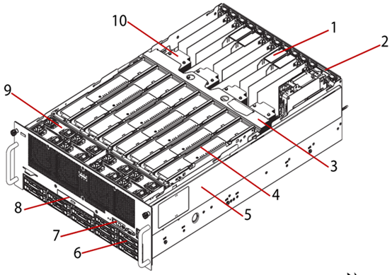
图 1-1 产品外观
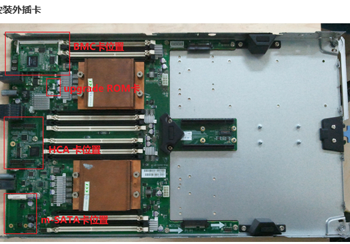
1. PCIE插槽*10,其中2,3,6,7槽支持热插拔。
2. I/O扩展卡&X540万兆网卡,原机到货时已安装在一起
3. 中间支架,可支持内存板安装
4.内存板,最多可支持8个,每个内存板可安装12个DDR3内存DIMM,支持Hot Add。内存板之间均通过有内存导风板隔开。
5. 机箱底座,4U高度
6. 硬盘托架*12,2.5寸,支持热插拔
7. 操作面板,包括3个按钮(电源、复位、ID)和4个LED灯(电源、ID、故障警示、硬盘)。
硬盘灯:常蓝—硬盘在工作,灯灭—硬盘在空闲状态;
故障警示灯: 琥珀色闪烁—侦测到有异常,灯灭—无异常;
ID灯:蓝色闪烁—侦测到有ID在活动,灯灭—未侦测到有ID在活动
电源灯:常蓝—系统已上电,灯灭—系统已关机
8. DVD光驱
9. 系统风扇*8,支持热插拔
10.CPU散热器
2. 前面板视图
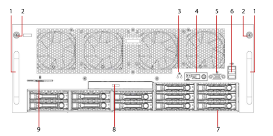
图 1-2 前面板示意图
| NO |
NAME |
DESCRIPTION |
| 1 |
Chassis handle |
Hold to remove chassis from the rack |
| 2 |
Thumb screw |
x2 thumb screws to secure chassis to rack |
| 3 |
Rear LAN LEDs |
Indicates LAN activity: LAN1: bottom LAN port on rear panel. LAN2: upper LAN port on rear panel. |
| 4 |
Operator panel |
Operator Panel includes the following:
|
| 5 |
Video connector |
Supports connection to external display. |
| 6 |
USB 2.0 |
x3 USB (2.0) connectors |
| 7 |
Hard disk drive bay |
2.5″ hot-plug hard drive bay (max. x12 HDDs). |
| 8 |
Optical disk drive |
DVD-RW player and writer. |
| 9 |
Asset tag |
Used to record system information, such as: MAC and IP addresses. |
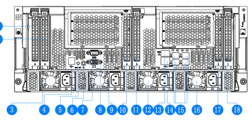
3. 后面板视图
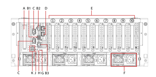
图 1-3 后面板示意图
| NO |
NAME |
DESCRIPTION |
| A |
SAS riser slot |
PCIe Gen-3×8,half length |
| B1 |
Video port – standard VGA compatible, 15-pin connector supporting up to 1920 x 1200 32bpp@60Hz resolution. |
|
| B2 |
Serial port |
|
| B3 |
I/O riser management Ethernet port (Aspeed AST2300) |
|
|
Managment port LED |
||
|
Status LED (bottom) – Green |
On – Link Blinking – Ethernet link is active Off – No Ethernet connection |
|
|
Speed LED (upper) Green / Amber |
Green On – 10 Mbps Amber On – 100 Mbps |
|
| C |
I/O riser dual gigabit Ethernet ports: Two LAN ports, RJ45 connector; bottom: LAN1, upper: LAN2 |
|
|
LAN port LED |
||
|
Status LED (bottom)-Green |
On – Ethernet link is detected Blinking – Ethernet link is active Off – No Ethernet connection |
|
|
Speed LED (upper) -Amber/Blue(dual color) |
Off – 10 / 100 Mbps Amber On – 1 Gbps Blue On – 10 Gbps |
|
| D |
Dual 10 gigabit Ethernet ports (optional, mezzanine installed to I/O riser module) |
|
| E |
Slot1: PCIe Gen-3×8 Slot6 PCIe Gen-3×8, hot-plug |
|
|
Slot2: PCIe Gen-3×8, hot-plug Slot7 PCIe Gen-3×16, hot-plug |
||
|
Slot3: PCIe Gen-3×8, hot-plug Slot8: PCIe Gen-3×8 |
||
|
Slot4: PCIe Gen-3×16 Slot9: PCIe Gen-3×8 |
||
|
Slot5: PCIe Gen-3×8 Slot10: PCIe Gen-3×8 |
||
| F |
Power supply unit, see PSU View on page 1-8. |
|
| G |
System ID button |
|
| H |
System ID LED: Blue ID identifies the system locally or through server management |
|
| J |
System status/fault LED |
|
| K |
USB ports (2.0) x2 |
|
4. 电源视图
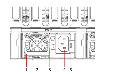
图1-4
| NO | NAME | DESCRIPTION |
| 1 | Handle | Hold to remove the PSU from the chassis bay. |
| 2 | Power supply fan | Do not cover to avoid system overheating. |
| 3 | PSU status LED | See Power Supply LED Definition on page 1-10. |
| 4 | AC input power connector | Connect power plug. 5 Release latch Press and hold to unlock PSU |
| 5 | Release latch | Press and hold to unlock PSU from chassis bay. |